
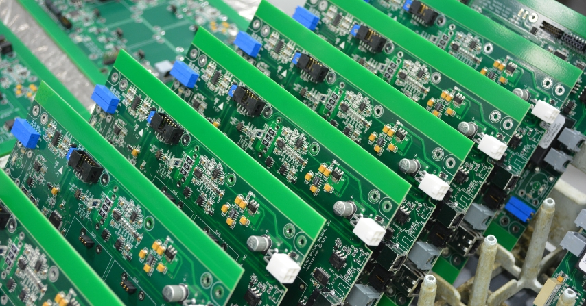
Double-Sided PCB Layout Tips for Reducing EMI and Crosstalk
In high-speed circuit design, electromagnetic interference (EMI) and crosstalk pose critical challenges that demand strategic PCB solutions. Double-sided PCBs provide engineers with essential tools to address these issues, offering dual-layer component placement and routing flexibility that significantly enhances signal integrity. By effectively separating analog and digital circuits across layers, these boards reduce noise coupling while improving electromagnetic compatibility – a crucial advantage for applications ranging from consumer electronics to industrial control systems. This article explores proven layout techniques to maximize the noise-reduction potential of double-sided PCBs, ensuring cleaner signals and more reliable performance in EMI-sensitive environments.
Noise Control Techniques for Double-Sided PCB Designs
The first line of defense against EMI and crosstalk is strategic component placement. Separating noisy components like switching regulators from sensitive analog circuits helps reduce interference. If necessary, these components can be placed on opposite sides of a double-sided PCB.
Also, grouping components by functionality—such as keeping high-speed logic away from analog sections—helps to control noise. Maintain short trace lengths between related components to prevent signal degradation. Ultimately, thoughtful placement can simplify the layout and improve the electromagnetic performance of your design.
Best Practices for Ground Plane Implementation on Double-Sided PCB
A continuous ground plane is vital in controlling EMI. On Double-Sided PCBs, designers often dedicate one layer primarily to ground. This strategy provides a low-impedance return path for signals, minimizing loop area and reducing radiation.
Additionally, avoid splitting the ground plane with signal traces, as it can create unintended antennas and noise paths. Stitch vias can connect both sides of the board for consistent grounding. By ensuring a stable reference ground, you significantly enhance noise immunity.
Optimizing Trace Routing to Minimize Coupling
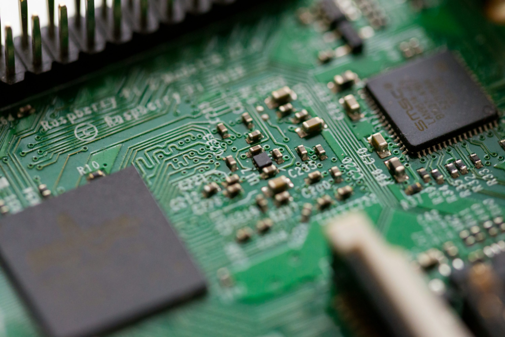
Trace routing is another critical factor in reducing EMI and crosstalk. On a double-sided PCB, use orthogonal routing, with horizontal traces on one side and vertical traces on the other. This method reduces parallel Coupling, a primary cause of crosstalk.
When routing high-speed signals, keep them short and direct. Avoid running traces in parallel over long distances, and maintain consistent spacing between them. These practices ensure that mutual inductance and capacitance remain within acceptable levels, preserving signal quality.
Controlled Impedance and Signal Return Paths
Maintaining controlled impedance is essential for high-frequency signal integrity. Use consistent trace widths and stack-up configurations to match the impedance required by the application. This is particularly important when routing differential pairs or clock lines.
Signal return paths must be as direct as possible in parallel. Provide return paths using ground vias or local planes if the ground plane is interrupted on a double-sided PCB. Avoid forcing return currents to take detours, which increases the risk of EMI.
Use of Decoupling Capacitors and Filtering Techniques
Decoupling capacitors help stabilize voltage levels and filter out high-frequency noise. For maximum effectiveness, place them close to the power pins of ICs. Multiple capacitors with different values can cover a wider frequency range.
Filtering components such as ferrite beads and RC networks can also suppress conducted noise. Place these components strategically near entry and exit points on a Double-Sided PCB. Combined, these techniques reduce emissions and susceptibility to EMI.
Shielding and Isolation Techniques
Physical and electrical shielding can significantly reduce EMI. Copper pours connected to the ground on a Double-Sided PCB can act as shields. For especially noisy areas, consider metal enclosures or canopies.
Isolation techniques, such as optocouplers or isolation transformers, can prevent noise transfer between different circuit sections. These methods ensure that high-voltage or noisy systems do not interfere with low-level analog or communication signals.
Testing and Simulation for EMI Compliance
Simulation tools can help identify potential EMI issues before fabrication. Use tools that analyze signal integrity and electromagnetic behavior. Early detection allows for quick adjustments to layout and routing.
After prototyping, perform lab tests using spectrum analyzers and near-field probes. Verify that both sides of a double-sided PCB contribute positively to EMI performance. Compliance testing ensures your product meets industry standards and avoids regulatory setbacks.
Mastering Double-Sided PCB Design for EMI and Crosstalk Control
A well-executed Double-Sided PCB design can dramatically reduce EMI and crosstalk, improving functionality and compliance. Engineers can enhance signal integrity and system stability by applying best practices in component placement, grounding, routing, and shielding.
As devices become faster and more compact, the importance of a bright PCB layout grows. Double-sided PCBs offer the flexibility to meet these demands without escalating costs. With continued innovation and careful design, you can future-proof your electronics and ensure they perform reliably in even the most challenging environments.