
What is the typical dielectric constant for Mid Low Loss PCB?
Understanding the dielectric properties is crucial when selecting printed circuit boards for high-frequency applications. Mid Low loss PCB are known for balancing performance and cost, making them popular in various electronic applications. This blog post will explore the typical dielectric constant for Mid Low loss PCBs, shedding light on its significance and implications for users and manufacturers.
Introduction to Mid Low Loss PCB
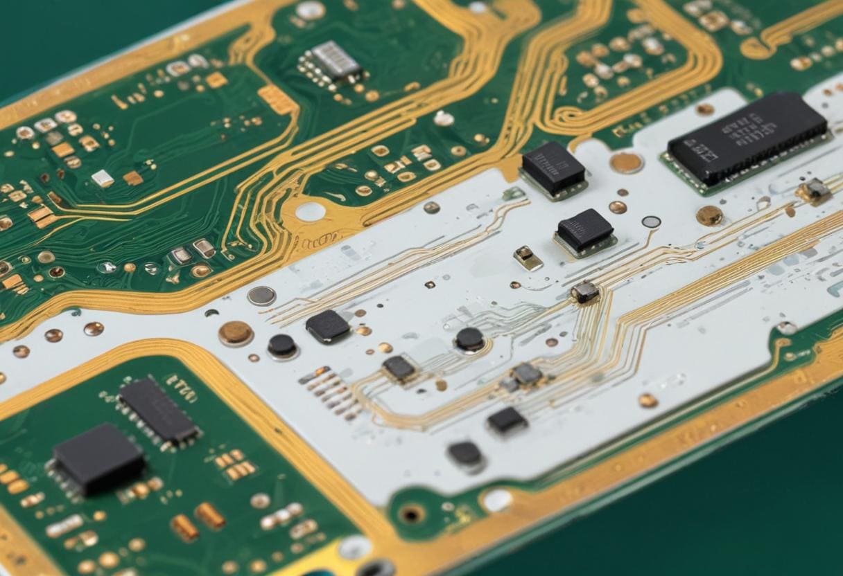
Mid Low loss PCBs are engineered to minimize signal loss while maintaining a reasonable cost. These boards typically feature a dielectric material that balances performance, loss, and manufacturing complexity. The dielectric constant in RF and microwave applications is pivotal in determining signal integrity and transmission efficiency. Understanding the dielectric constant helps users select the correct PCB for their needs.
The typical dielectric constant for Mid Low Loss PCBs ranges from 3.0 to 5.0. This range allows for good performance across various frequencies while ensuring that the signal loss remains manageable. The choice of materials and their dielectric properties directly influence the performance characteristics of the PCB, making it essential to consider these factors during the design phase.
The Importance of Dielectric Constant in PCB Design
The dielectric constant measures a material’s ability to store electrical energy in an electric field. For PCBs, this property affects various performance aspects, including signal propagation speed, impedance, and overall signal integrity. A lower dielectric constant generally leads to higher signal speed and lower capacitance, which is beneficial in high-frequency applications.
Understanding the dielectric constant helps engineers optimize the layout and performance of the circuit when designing with Mid Low loss PCBs. The dielectric constant influences the transmission line characteristics, which are critical in maintaining the integrity of high-frequency signals. Designers can ensure efficient signal transmission with minimal loss by selecting a dielectric material with the appropriate constant.
Factors Affecting Dielectric Constant
Several factors can influence the dielectric constant of Mid Low Loss PCBs. Material composition is primary; different substrates and fillers can significantly alter the dielectric properties. For example, specific polymers, ceramics, or composite materials can adjust the dielectric constant to achieve desired performance characteristics.
Environmental conditions like temperature and humidity also affect the dielectric constant. The dielectric constant can change as the temperature increases, affecting the PCB’s performance. Understanding these variables is essential for manufacturers and designers to ensure that the PCBs perform reliably under varying conditions.
Effect of Manufacturing Materials on Dielectric Constant
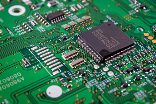
The materials selected for Mid Low Loss PCBs directly impact their dielectric constant. Common materials include FR-4, PTFE, and various composite materials. FR-4, a widely used fiberglass-reinforced epoxy laminate, typically has a dielectric constant of around 4.2, making it suitable for many applications.
PTFE, known for its low dielectric constant (approximately 2.1 to 2.5), is often used in high-frequency applications due to its excellent performance characteristics. Composite materials can be engineered to achieve specific dielectric constants, allowing for greater flexibility in design. Understanding these materials’ properties helps users choose the correct application PCB.
Evaluate the effect of dielectric constant on its functionality
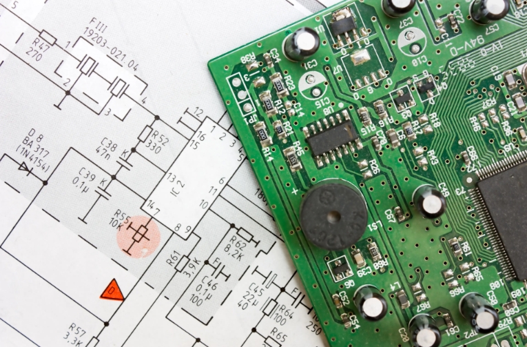
Evaluating how the dielectric constant impacts the functionality of mid low loss PCBs is crucial to ensuring optimal performance. Performance is often assessed using parameters such as return loss, insertion loss, and phase stability. These metrics indicate how well the PCB transmits signals without significant degradation.
Testing the PCB under various conditions helps determine its effectiveness in real-world applications. By analyzing these performance characteristics, manufacturers can refine their designs and materials, ensuring that the dielectric constant aligns with the performance requirements of the intended application.
Choose the correct application scenario
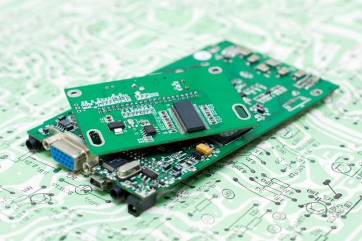
Mid Low loss PCBs are utilized in various applications, including telecommunications, automotive electronics, and consumer devices. The typical dielectric constant of 3.0 to 5.0 makes these PCBs versatile for many frequency ranges, particularly in RF and microwave applications.
In telecommunications, for instance, Mid Low loss PCBs help facilitate efficient data transmission, which is critical for maintaining network reliability. Automotive electronics benefit from these PCBs as they support various functions, from radar systems to infotainment, where signal integrity is paramount—understanding the dielectric constant aids in selecting the correct PCB for each application.
Future Trends in Mid Low Loss PCB Technology
As technology advances, the demand for Mid Low Loss PCBs with specific dielectric properties will likely grow. Innovations in material science are paving the way for substrates with tailored dielectric constants that meet emerging industry needs. These advancements will allow for even higher frequencies and more efficient signal transmission.
Manufacturers increasingly focus on developing materials that can withstand higher temperatures and harsher environments while maintaining favorable dielectric properties. This trend indicates a move toward more durable, reliable Mid Low Loss PCBs that can adapt to evolving technological demands.

The Role of Dielectric Constant in Mid Low Loss PCB
Typical dielectric constants for Mid Low Loss PCBs range from 3.0 to 5.0, balancing performance and cost for various applications. By understanding the factors that affect dielectric performance and evaluating the materials used, stakeholders can make informed decisions that improve the performance and reliability of their electronic systems. As technology evolves, the role of dielectric constant in PCB design will continue to be a key consideration in achieving optimal results.